Embedded Process
Integration and Soldering Guidelines M1575HCT-22-P Tuning Kit
The degree of integration and components density in mod-ern wireless enabled devices has increased dramatically as integrated circuits have become more powerful and smaller in size. At the same time the integration process of antennas into these devices has become a non-trivial engineering challenge that requires multidisciplinary skills and costly customization. The antenna performance is in fact very much affected by noise, interference and detun-ing produced by surrounding components.
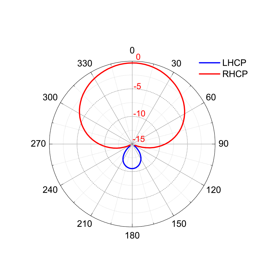
The quadrifilar helix antenna is recognized as possibly the best GPS antenna thanks to its characteristics. It has a cardioid-shaped conical pattern, a high front-to-back pattern ratio, and good circular polarization characteristics. It consists of four equally spaced metallic arms that are wrapped around a cylindrical surface, forming four equally spaced helices. A feeding network provides signals to these helices with proper phasing to generate the desired radiation pattern. Different types of printed quadrifilar helix antennas (PQHAs) have been proposed as antenna solu-tions for mobile satellite communication systems. These antennas are preferred to crossed dipoles and patches for their small structure, insensitivity to ground or hand prox-imity effects, flexibility in shaping radiation pattern, and wide circularly polarized beam. Printed quadrifilar anten-nas are also usually preferred over wired quadrifilar anten-nas since they offer the advantages of lightweight, low cost, high-dimensional stability, and ease of fabrication.
Size and weight are very often the key constraints for portable hand held terminals and have been driving the development of smaller and lighter antennas over the last couple of decades. Size reduction for PQHA has tradition-ally been obtained by printing the antenna on a cylinder with high-dielectric permittivity, like ceramic. However. the dielectric constant of ceramic materials is difficult to control during mass production, and the batch to batch consis-tency can often be very poor. This variation in the dielectric constant requires individual tuning of the antennas with significant impact on the production costs.
Maxtena has developed a family of high performance PQHAs based on its proprietary HeliCore® technology. This technology provides an extremely flexible platform for fitting different products with varying specifications in terms of patterns, polarization, efficiency and size. The antenna size reduction is based on the miniaturization and optimization of the feeding network, hosted on a small printed circuit board, while the antenna element can be realized as a flexible printer circuit (FPC) wrapped around a cylindrical plastic support. The absence of ceramic materials allows for tighter control of the antenna center frequency and provides better consistency during mass production. Moreover, HeliCore® technology is based on the functional decoupling between the antenna element and the feeding network, resulting in a radiation pattern that maintains the same characteristics over a very wide bandwidth, well beyond the impedance bandwidth of the antenna itself.
The unique characteristics of the HeliCore® technology ensure high performance and straightforward integration under the most demanding constraints. Obviously, early consideration of the antenna integration in the design process is always the best approach and leads to optimal results in terms of cost and performance. The biggest challenge is in minimizing the interference between the antenna and other components so that the radiation per-formance is not compromised.
To provide customers with an inexpensive, quick and ef-fective way to determine the correct GPS antenna to use for their specific device, Maxtena offers a tuning kit based on the M1575HCT-22-P antenna. The M1575HCT-22-P is the smallest antenna among the Maxtena HeliCore® family and it is unmatched in the industry in terms of perfor-mance, size, reliability and weight.
By removing the need of a lengthy and costly custom antenna integration process in a particular device, the use of the tuning kit can drastically shorten the time to market of new products while guaranteeing a high performing antenna.
This document describes the mechanical and electrical characteristics of the Maxtena M1575HCT-22-P tuning kit and provides a detailed guidance on how to use it. performance has to be monitored in terms of the values of the 4-5 highest carrier-to-noise ratio (C/No) received from the GPS satellites. A step-by-step example of the evalu-ation procedure is provided on pages 7-10 of this docu-ment. When placing the order for production quantities, the customer should specify the desired element among the tuning kit by its correspondent color code.
GPS HELICORE® TUNING KIT
The Maxtena GPS HeliCore® tuning kit contains five stan-dard quadrifilar helix samples (identified by color codes, see Fig. 1) optimized for a range of different loading condi-tions commonly encountered in devices requiring an em-bedded antenna configuration. Since the effect of dielectric loading and printed circuit board edge proximity produces a downward shift of the center frequency, the antennas in the kit are tuned at incrementally higher frequencies than the nominal GPS L1 center frequency. The elements in the kit provide the ability to obtain high radiation gain for the vast majority of modern GPS devices.
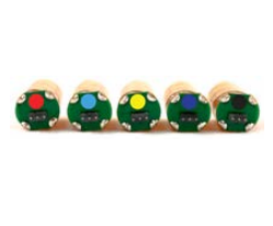
Each color corresponds to a different tuning frequency. The five antennas are also identified by a different suffix in the part number ranging from E1 to E5 as summarized in Table 1.
In order to select the suitable element in the kit, the cus-tomers should properly install the five antennas on the target device one by one and determine which provides the optimal performance: for each antenna the GPS signal performance has to be monitored in terms of the values of the 4-5 highest carrier-to-noise ratio (C/No) received from the GPS satellites. A step-by-step example of the evalu-ation procedure is provided on pages 7-10 of this docu-ment. When placing the order for production quantities, the customer should specify the desired element among the tuning kit by its correspondent color code.
| Red (R) / M1575HCT-22-P-E1 | |
| Blue (B) / M1575HCT-22-P-E2 | |
| Yellow (Y) / M1575HCT-22-P-E3 | |
| Purple (P) / M1575HCT-22-P-E4 | |
| Black (K) / M1575HCT-22-P-E5 |
Customers should contact Maxtena if optimization or pre-cise antenna tuning is still needed after the initial screen-ing process.
Electrical Specifications
HeliCore® technology has been successfully implemented in a variety of products in the satellite telephony and GNSS markets, and it has become the leading solution in terms of size, weight and performance. The key character-istic of this technology is the functional decoupling of the radiating element and the feeding network. The former is responsible for radiating power, and the latter controls fine tuning, patterns, and polarization. The functional decou-pling between these two structures enable the feeding net-work on the PCB to dominate the impedance characteris-tics of the antenna, masking the actual resonant response of the antenna element. Accordingly, an extremely flexible platform is obtained, which can fit different products with varying specifications in terms of patterns, polarization, efficiency and size.
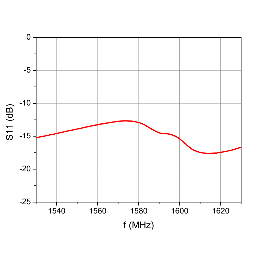
A corollary of the HeliCore® design approach is that the input impedance of the antenna is dominated by the feed-ing network, masking the resonant behavior of the antenna itself. It is not possible therefore to directly determine the resonant frequency of the antenna by looking at the input reflection coefficient (or VSWR). A full characterization in an anechoic chamber is necessary.
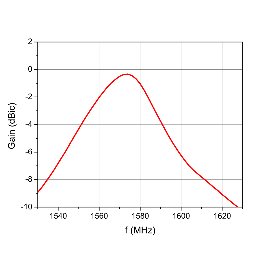
The typical radiation properties and the input behavior of a M1575HCT-22-P antenna are reported in Figs. 2 through 5 and summarized in Table 2. In this particular case, the antenna is tuned at 1575 MHz, as shown in Fig. 2. If the gain as function of frequency is compared with the input reflection coefficient Fig. 3, it is clear that there is no direct correlation between the latter and the antenna center frequency.
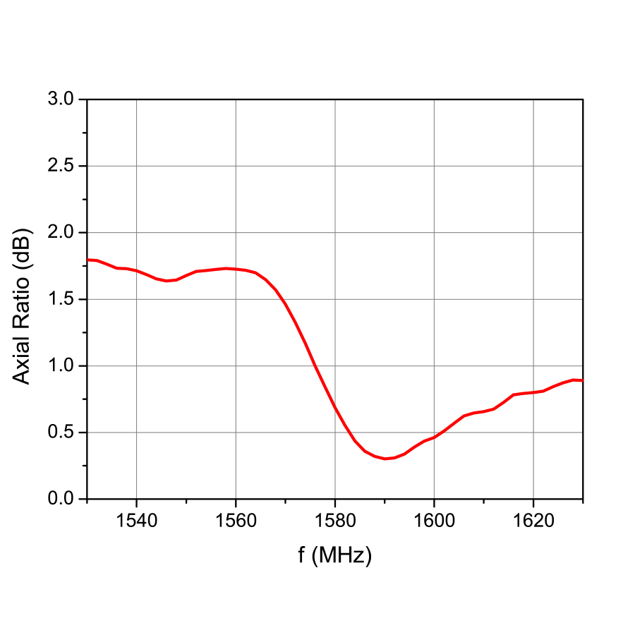
Within a -3dB gain bandwidth of about 35 MHz, the M1575HCT-22-P antenna offers a very good polarization purity over a wide frequency range (see Fig. 4), which is a distinctive characteristic when compared with a patch an-tenna. As a result, the radiation pattern is nearly constant over frequency with the canonical cardioid shape and a negligible LHCP component, as shown in Fig. 5.
| Parameters | Design Specifications |
|---|---|
| Polarization | RHCP |
| Gain | -0.5 dBic |
| Efficiency | 30% |
| Axial Ratio | 1 dB |
| Bandwidth (-3dB) | 1 dB |
| Beamwidth | 126˚ |
| VSWR | 1.5 |
| Impedance | 50 Ohm |
Maxtena M1575HCT-22-P is nominally matched to 50 Ohm with a VSWR less than 2. The antenna RF output pin presents a DC short, which can cause problems to the receiver if the RF port of the receiver is used to sup-ply DC power. The problem can be easily addressed by using a bypass capacitor as indicated in the schematic in Fig. 6. The value of the bypass capacitor should be larger than 20 pF to minimize effect on RF input impedance. NO INPUT IMPEDANCE MATCHING should be attempted when using M1575HCT-22-P. The input impedance of the antenna is dominated by the feeding network character-istics. Any external matching is going to have no effect on the actual antenna tuning.
The antenna comes with a 3-pin connector meant to be soldered on the host PCB or plugged into the recommend-ed female socket. The center pin carries the RF signal, while the side pins should be connected to ground, as shown in the schematic below.

Mechanical Specifications
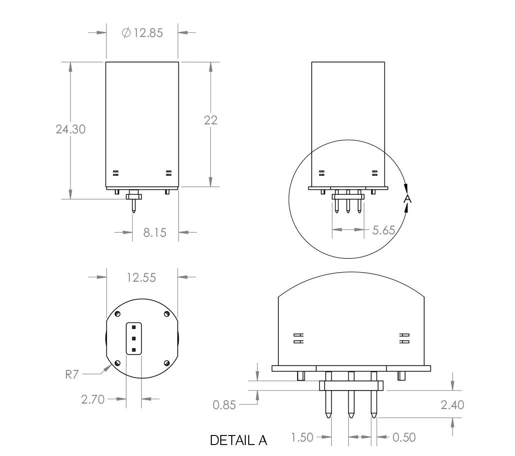
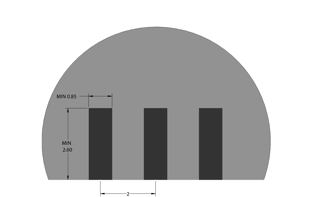
The five Maxtena M1575HCT-22-P antennas present in the tuning kit have the same mechanical dimensions, and only can be identified by the color marks on the bottom of the board. The standard electrical interface is a 3-pin male connector with 2mm pitch and 0.5mm square pins that can be hand soldered directly to a PCB or connected to a female socket. Any standard 2mm pitch socket accepting the same pin size can be used. For edge mounted appli-cations Maxtena suggests using Gradconn BB02-RW032-K03-000000. The detailed dimensions of the antenna are described in Fig. 7, and the recommended PCB footprint for the 3-pin connector is illustrated in Fig. 8.
A 3-D CAD model of the antenna is available in STEP format upon request.
INTEGRATION GUIDELINES
Unlike most components used in electronic devices, the behavior of antennas is very much affected by the nature and shape of materials and components in their proxim-ity. The electromagnetic fields from an antenna interact with nearby objects that in turn determine its frequency of operation. The antenna must be carefully optimized for its actual operational environment, taking into account its positioning and dielectric loading. A detuned antenna can degrade the link budget by 10-30 dB and severely reduce range.
Positioning
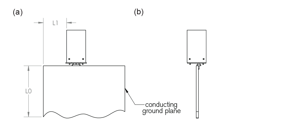
When integrated in a device, an antenna is usually mounted along the edge of a PCB or perpendicularly to it (see Fig. 9(a)). In both cases, the M1575HCT-22-P tuning is not affected by the size and shape of the PCB, provided that no metallic or plastic objects are located around the antenna. In general, the dimensions L0 and L1 have little effect on the antenna frequency characteristics. However a vertical metallic wall, as in the case shown in Fig. 9(b) could degrade the performances of the M1575HCT-22-P: a distance (L3) from the vertical wall larger than 5 mm is suggested to avoid de-tuning effects (see Fig. 9(b)). It is important noted that any object breaking the rotational symmetry around the M1575HCT-22-P, as in the case of the vertical wall, will cause a degradation of the axial ratio, symmetry of the pattern in azimuth and de-polarization.
Dielectric loading
The antenna tuning and its radiation pattern also depend on the plastic cover that protects and holds it inside the device. In this section we offer tuning guidelines in the case of a rotationally symmetric dielectric loading. As shown in Fig. 10, the M1575HCT-22-P is enclosed in a cylindrical shell of thickness T and external diameter D. An air gap G is present between the plastic cylinder and the lateral surface of the antenna.
As the dielectric constant of the housing varies together with its geometrical parameters, the antenna tuning fre-quency changes. Four tables corresponding to four differ-ent values of the dielectric constant of the housing (ε= 2.2, 2.7, 2.9 and 3.7) have been generated for quick reference. The tables can be used as guidance for choosing which antenna in the tuning kit to use for different values of the geometrical parameters. The letters R, B, Y and P in the table indicate the color code of the antennas in the tuning kit (see Table 1).
General Recommendations
In general, it is good practice to design the device plastic cover as symmetrical as possible around the antenna to obtain a better axial ratio and radiation pattern rotational symmetry. It is also recommended that possible sources of noise, e.g., LCD drivers, cameras, are either kept as far away as possible from the antenna or properly shielded to avoid interference.
SELECTING ANTENNA STEP-BY-STEP
The example described in this section is meant to show how to practically use the M1575HCT-22-P tuning kit. In particular, it is shown how to select the antenna variation in the tuning kit the most suitable for the specific plastic enclosure.
Before starting the test, a prototype of the device hosting the antenna should be available, including the PCB, all the metal parts and the plastic components that are in prox-imity of the antenna location. The antenna can be either installed directly on the PCB by hand soldering or using a SMT female connector as described in the mechanical specifications section. Please read the soldering instruc-tions reported in the Appendix for the former case. After the installation is completed, the test can start: the testing procedure has to be exactly repeated for each antenna in the kit.
The signal from the antenna can be either routed to the GPS receiver on the same board, as in the intended use mode, or to an external receiver, by using a coaxial cable. In the latter case, a DC block or Bias T should be used to avoid damaging the receiver. In fact, most of the stand-alone receivers supply a DC voltage through the RF port. Since the input of the antenna is designed as a DC short, the receiver could be damaged if a decoupling block is not used.
An example of the PCB with an installed element and a pigtail coaxial cable attached to it is shown in Fig. 11 for reference.
In the present example, for sake of simplicity, a cylindrical plastic radome, completely covering the antenna element is considered. The tuning variation in the kit that is tuned at GPS frequency in the presence of the plastic cover it is not known a priori. Table 3 can be used for an initial guess and to verify that the dielectric loading under consideration is within the usable range.
In this example, a u-Blox 6 (model EVU-6H-0-001) evalu-ation kit receiver is used. The receiver comes with its software (u-Center) that allows real time monitoring of dif-ferent metrics. In this particular case, the metric of interest is the intensity of the C/No received from the GPS satel-lites. A proper operation of the u-Blox 6 receiver requires a peak of C/No above 40 dB for at least some of the high elevation satellites. For this reason, the 4 or 5 highest values of C/No are monitored and recorded during the test procedure for each antenna of the tuning kit. The antenna with the best C/No values (above 40 dB) is the antenna that should be selected. It has to be noted that different receivers might require different peak value of C/No to properly operate.
The test starts by connecting the receiver to a laptop run-ning the u-Center software. It is important to make sure that the communication is established between the laptop and the receiver. The test has to be performed outdoors in a location with an unobstructed view of the sky. It is also important to remember to install the DC block with coaxial cable extension. In this case an ad-hoc transition between SMA and the antenna 3-pin connector has to be used. As already stated, the kit contains four elements that are color coded with Red (R), Black (K), Blue (B), Yellow (Y) and Purple (P) as listed in Table 1. The test can start with any antenna in the kit, e.g. the one marked with the red color. This antenna is placed inside the plastic cover and connected to the receiver.
Once the u-Center software is opened, a cold start proce-dure has to be run and all the history data erased to reset the signal averaging performed by the software. For each test a cold start should be forced and all the accumulated data reset, regardless of the software utility used. This ensures that the current test is not affected by previous ones. At this point the test can start. In order to record data for all the antennas present in the tuning kit, the values of C/No and number of satellites in view has to stabilize. The 4 or 5 highest values of C/No are then recorded for the antenna being tested.
The next antenna in the kit, e.g. Black, is then installed and the test procedure is repeated.
When all the antennas have been tested, the C/No values are compared and the elements providing the highest number of C/No above 40 dB should be selected. Differ-ent receivers could provide different C/No values. In most cases, only one of the antennas in the tuning kit provides reading for C/No above 40, making the selection quite unambiguous.
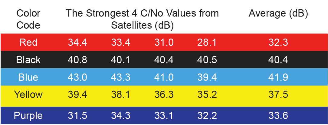
In this example, the values of C/No from each antenna of the kit are summarized as following:
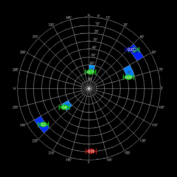
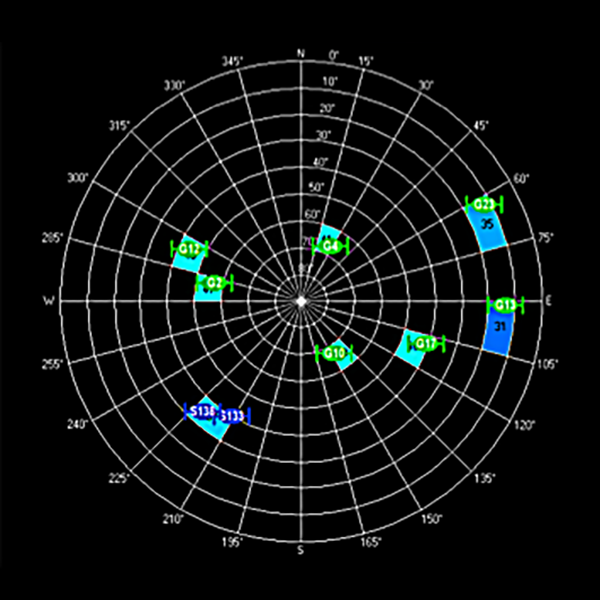
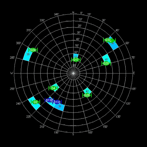
The corresponding sky view and instant C/No values are shown in Fig. 13 and 14. In general, as the value of C/No increases, a larger number of satellites can be visualized.
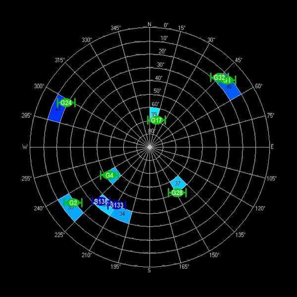
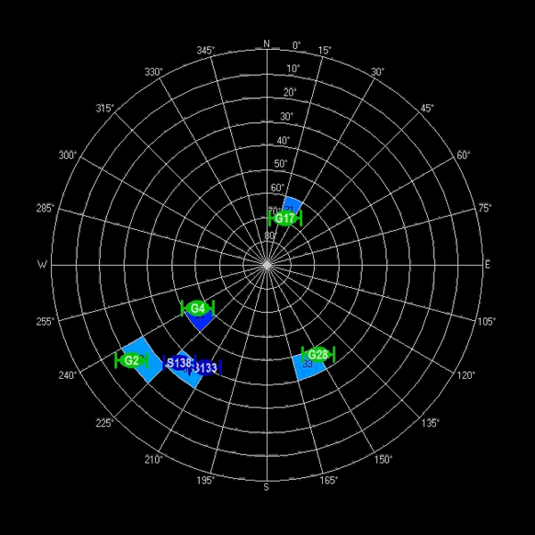
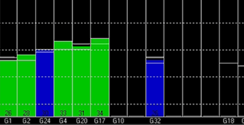
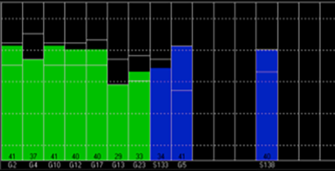
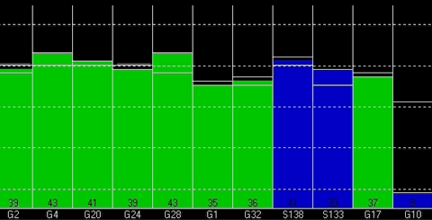
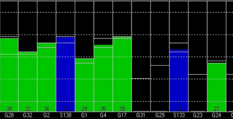
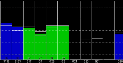
A relative measure of performance between elements can be estimated by averaging the 4-5 highest values of C/No. The average should be performed in linear scale, after converting the C/No values from dB. The average can then be expressed back in dB [10 log10()]. The difference between averages is correlated with the difference in gain at 1575 MHz between the elements, when loaded with the desired enclosure.
Clearly, in this example, the Blue element provides the strongest C/No among the kit, and it is the antenna in the tuning kit to be selected for the given plastic cover.
Recommended Equipment:
1.) A soldering iron with a fine tip (1mm ± 0.2mm) may be used.
2.) An assembly jig to maintain proper alignment and sup-port of the work piece is also recommended.
Temperature Profile:
The recommended temperature range or the soldering iron is 400°C ± 25°C for a dwell time not to exceed 5 seconds.