Antenna Integration Guidelines
Introduction
Maxtena is advanced in customization of a wide range of antenna types for drone applications. We deliver the edge of RF technology to customer in aerospace and undammed drone applications. We know customer requirements and give you our valuable experience based on more than 15 years of experience to place the antenna inside our customers housing. We optimize our antenna inside our customers housing to improve C/N, axial ratio and desense of GPS antenna in the whole frequency band. Our recommendations are categorized in mechanical and electrical parts. Mechanical suggestions help customers to choose low loss and stable materials. We recommend the best housing material to customers that pass all their specifications. The recommended materials have mechanical stabilities with low electrical loss. The recommended materials have minimum effect on the antenna performance and the antenna can receive maximum signal power from satellite. Electrical antenna recommendations give customer feedbacks to have better idea to place other antennas like WiFi, LTE, and boards (ground plane) beside our antenna.
GPS antenna accuracy
For GPS applications antenna axial ratio is a critical parameter that determine the user position. Ground plane or electronic board can deteriorate the antenna axial ratio (AR) and antenna precision. One typical parameter to measure accuracy is called Dilution of precision (DOP). DOP is a mathematical term that describes how the errors in measurement and the geometry of navigation satellites that the receiver sees affect the positional measurement precision. It can be defined as:

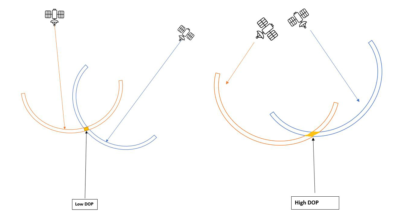
A GNSS receiver usually requires only four satellite signals to provide a complete positional fix in three dimensions. The accuracy of this fix depends to some degree on the exact positions of the four satellites relative to the receiver. If the four signals acquired come from satellites spread throughout the sky relative to the receiver, then the fix will be highly accurate. But if all four satellites are close to each other within a single quadrant, then the fix will be less accurate. If two or more satellites are aligned and to appear to occupy the same space, then it may be impossible to obtain any fix. Alternatively, the fix obtained may be out to the tune by 150 or even 200 meters. When visible navigation satellites are close together in the sky, the geometry is said to be weak and the DOP value is high; when they are far apart, the geometry is said to be strong, and the DOP value is low. Hence, a low DOP value represents a better positional precision due to the wider angular separation between the satellites used to calculate a GNSS receiver unit's position. The more scattered and the farther away the satellites are DOP is better. That relationship is shown in with a simple 2D example:
Position (3D) DOP (PDOP): This value describes how many satellites are spread evenly throughout the sky. The more the satellites directly above and the less on the horizon, the lower the PDOP value is.
Horizontal DOP (HDOP): This describes the effect of DOP on the horizontal position value. The better visible satellites low in the sky, the better the HDOP and the horizontal position (Latitude and Longitude) are.
Vertical DOP (VDOP): This refers to the effect of DOP on the vertical position value. The better visible low satellites in the sky, the better the VDOP and the vertical position (Altitude) are.
Time DOP (TDOP): This value describes the difference in time values of the satellites and receiver’s internal clocks. The more in sync their clocks are the lesser the TDOP value.
The lower the value of DOP is the greater the confidence in the output location is. This table shows the interpretation of the DOP Values.
Interpretation of DOP Values
| DOP Value | Rating | Description |
|---|---|---|
| < 1 | Ideal | Highest possible confidence level to be used for applications demanding the highest possible precision at all times. |
| 1-2 | Excellent | At this confidence level, positional measurements are considered accurate enough to meet all but the most sensitive applications. |
| 2-5 | Good | Represents a level that marks the minimum appropriate for making accurate decisions. Positional measurements could be used to make reliable in-route navigation suggestions to the user. |
| 5-10 | Moderate | Positional measurements could be used for calculations, but the fix quality could still be improved. A more open view of the sky is recommended. |
| 10-20 | Fair | Represents a low confidence level. Positional measurements should be discarded or used only to indicate a very rough estimate of the current location. |
| > 20 | Poor | At this level, measurements are inaccurate by as much as 300 meters with a 6-meter accurate device (50 DOP × 6 meters) and should be discarded. |
We also optimize the gap and distance of our antennas result to the customer housing based on the simulation and measurement results to minimize DOP of the GPS antenna. The recommended gap should be at least 4mm from the ground plane to the antenna board.
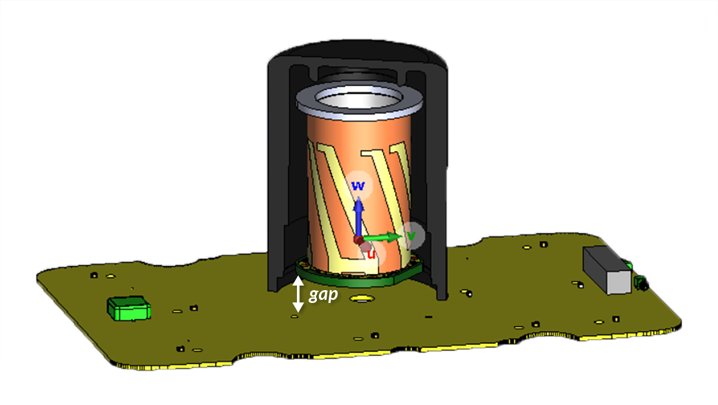
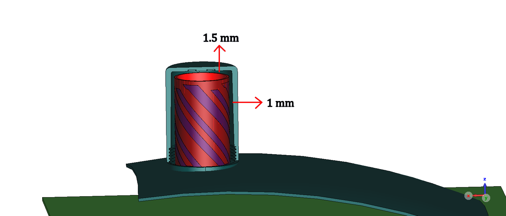
To achieve maximum received signal from the satellite and reduce the reflection we test our antennas with different customer housings. The best results can be achieved when the air gap from the side and top of the antenna are considered 1 mm and 1.5 mm respectively as shown.
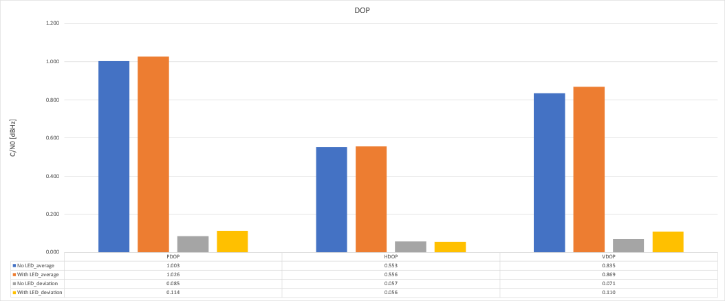
DOP results comparison of measurements with and without matrix is shown for M1227HCT-A2-SMA.
GPS antenna tolerance against aggressor signals
The interference is one of the most challenges customer encounter when the GPS antenna places near the Wi-Fi antennas.
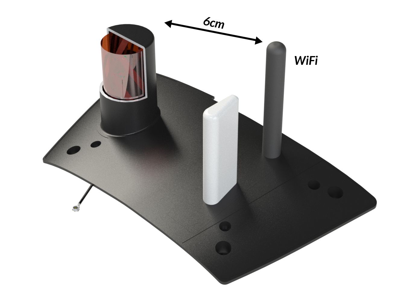
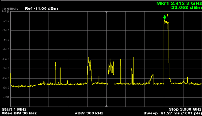
The WIFI antenna distance to the quad is about 6 cm. As shown as follows, the aggressor Wi-Fi antenna transmits a signal at 2.4 GHz and the receive power in the GPS antenna is about -23dBm. The transmitter power is 0 dBm. We recommend customers to place the wifi antenna at least 6 cm further from the GPS antenna.
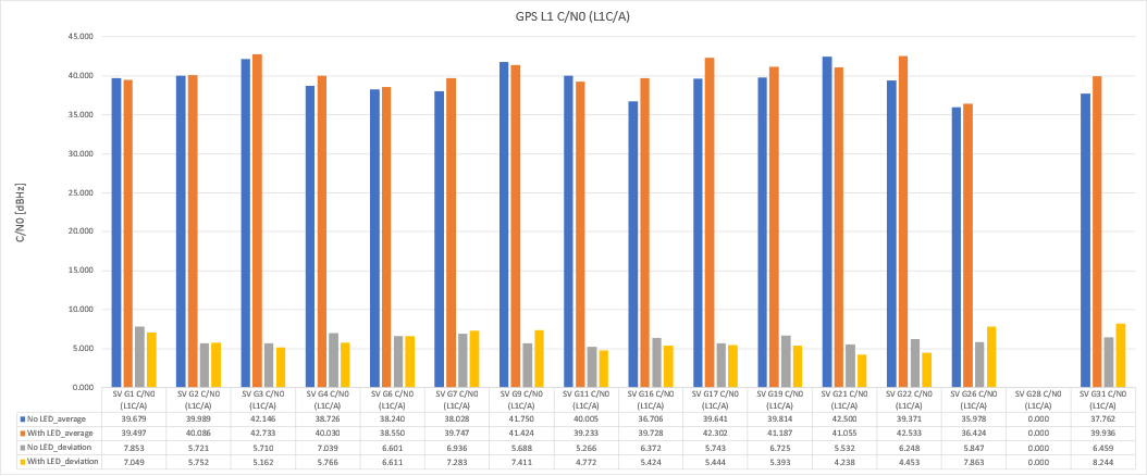
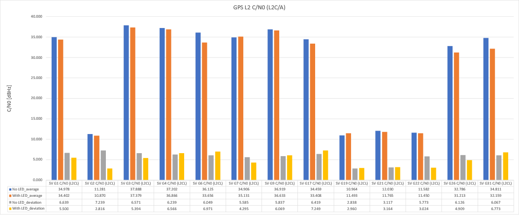
GPS antenna carrier to noise (C/N)
In satellite communications, carrier-to-noise-density ratio (C/N0) is the ratio of the carrier power C to the noise power density N0, expressed in dB-Hz. The higher C/N0 is better. The typical C/N0 value of an ideal GNSS receiver range from 37 to 45 dB-Hz. These values vary by using different antenna sizes and housings.