Antenna Specifications
Frequency
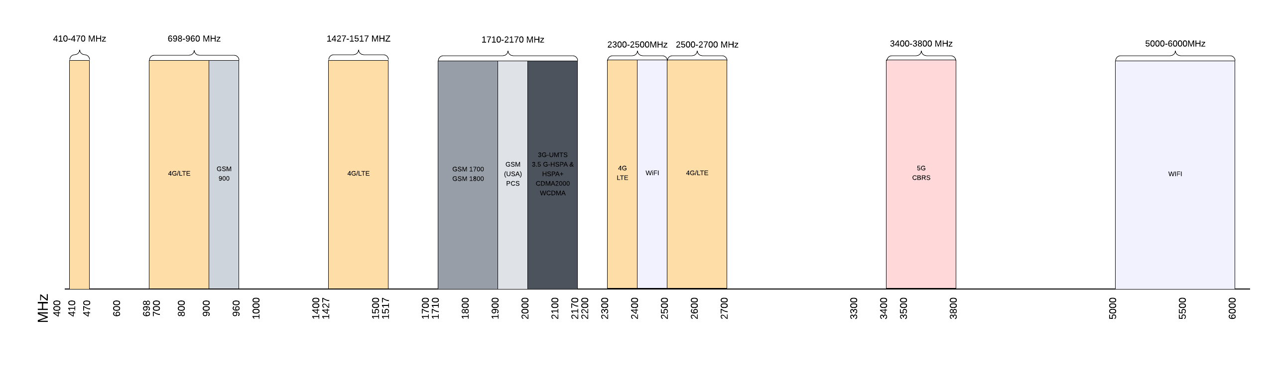
The frequency of an antenna is the range of radio frequencies it can transmit or receive. Antennas are designed to operate over a specific frequency range, and their performance can vary depending on the frequency of the signal they are transmitting or receiving. The specific frequency range of an antenna is determined by its design and construction.
Efficiency
Antenna efficiency is a measure of how effectively an antenna converts input power into radiated power. It is typically expressed as a percentage and is calculated by dividing the radiated power by the input power and multiplying by 100. A highly efficient antenna will radiate most of the input power, while a less efficient antenna will radiate less power and may suffer from losses due to resistance or other factors. Antenna efficiency is an important factor to consider when designing and selecting antennas, as it can affect the performance and range of a communication system.

Polarization
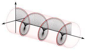
Antenna polarization refers to the orientation of the electric field of the EM waves that an antenna transmits or receives. Antennas are typically designed to transmit and receive radio waves with a specific polarization, which can be either vertical, horizontal, or circular. The polarization of an antenna is determined by the orientation of its elements relative to the ground. For example, a vertical antenna will have elements that are oriented perpendicular to the ground, while a horizontal antenna will have elements that are oriented parallel to the ground.
Right-hand circular polarization
Right-hand circular polarization (RHCP) is a type of polarization in which the electric field of the radio wave rotates in a clockwise direction as it propagates. This is the opposite of left-hand circular polarization (LHCP), in which the electric field rotates in a counterclockwise direction. Circular polarization is often used in satellite communications, as it can provide better performance in environments with significant amounts of atmospheric noise or interference. Antennas that are designed to transmit or receive RHCP signals have elements that are arranged in a circular pattern, with the elements oriented in a specific way to produce the desired polarization.
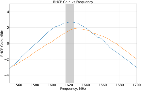
Antenna Gain
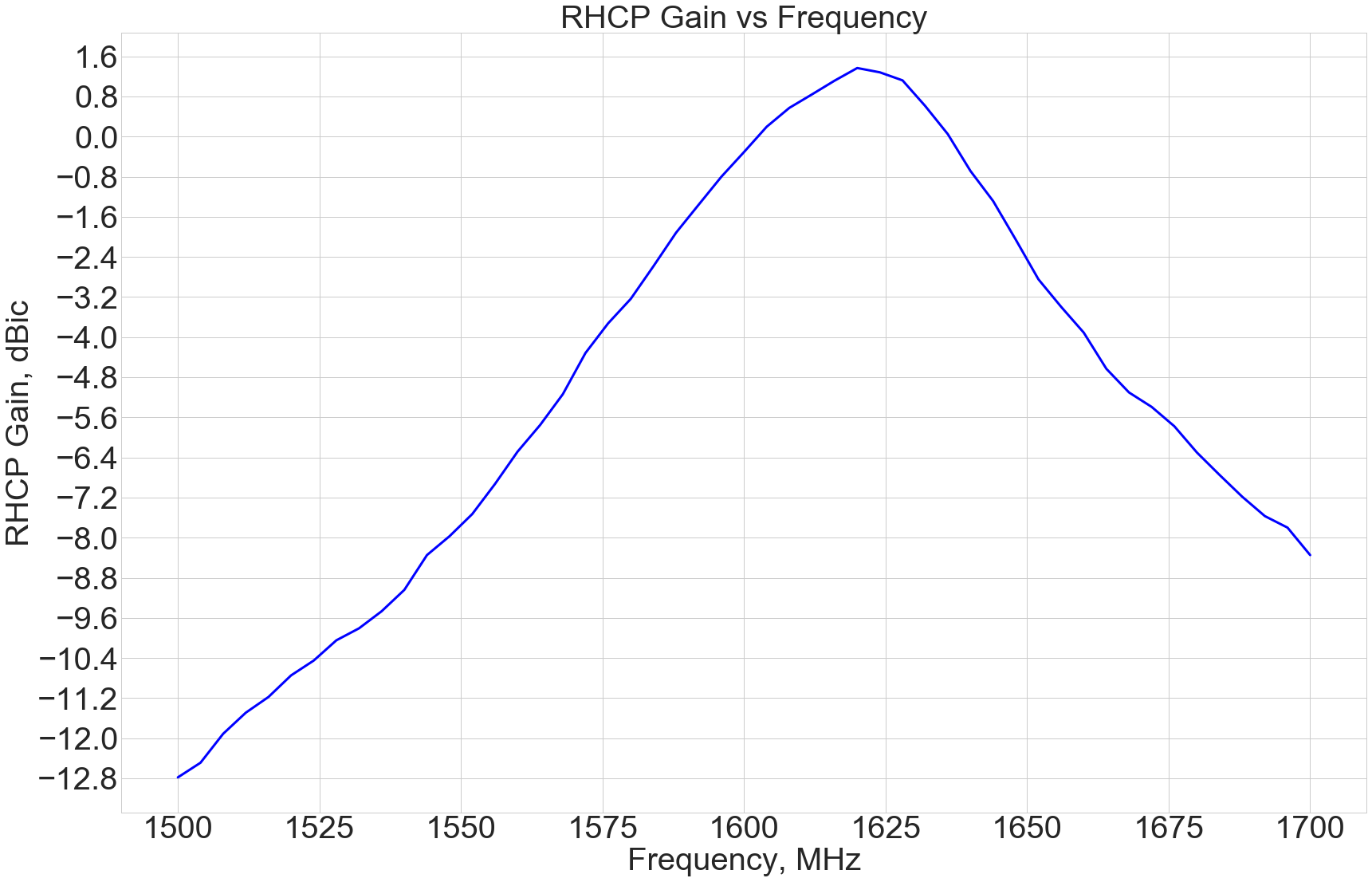
Antenna gain is a measure of the increase in the strength of a radio signal as it passes through an antenna. It is typically measured in decibels (dB). Antennas with a high gain will amplify the input signal and radiate it over a larger area, while antennas with a low gain will produce a weaker signal. Antenna gain is often used to compare the performance of different antennas and can be an important factor to consider when selecting an antenna for a particular application.
Axial Ratio
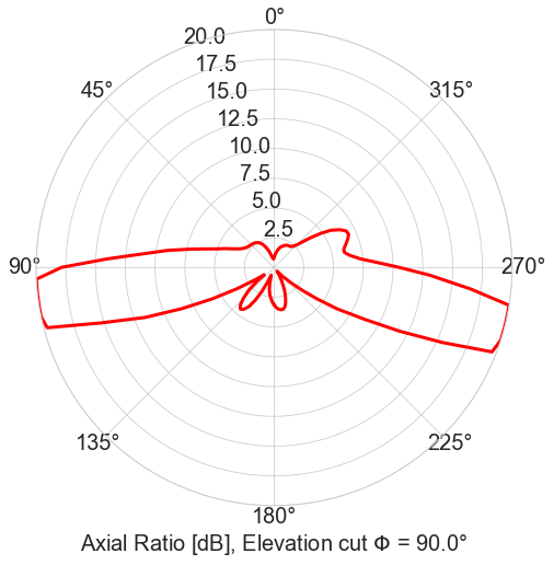
The axial ratio of an antenna is a measure of the ellipticity of its radiation pattern. It is defined as the ratio of the major axis to the minor axis of the antenna's radiation pattern in a given plane. The axial ratio is typically expressed in decibels (dB), and is often used to evaluate the performance of circularly polarized antennas. A perfect circularly polarized antenna will have an axial ratio of 0 dB, while an antenna with an axial ratio greater than 0 dB will have an elliptical radiation pattern. The axial ratio of an antenna can be affected by factors such as its design, construction, and operating environment.
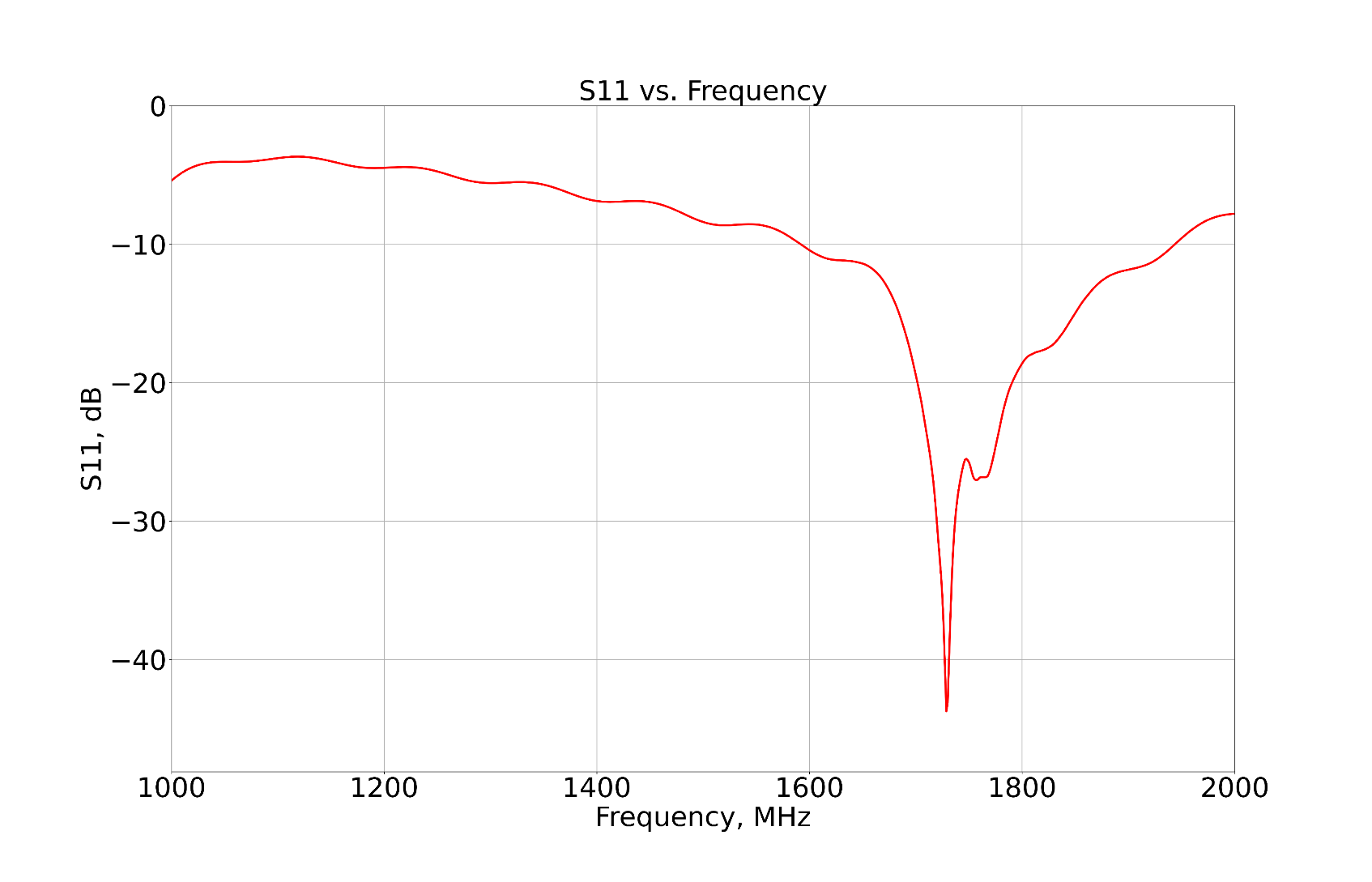
Return Loss
Return loss is the parameter that describes the amount of the power reflected back towards the source as a result of standing waves on the transmission line caused by mismatched antenna and/or mismatched line. It is a measure of how well an antenna is able to transmit or receive a signal. Return loss is typically expressed in decibels (dB). A good antenna will have a return loss typically less than -10 dB over working frequency range, which indicates that it is able to efficiently transmit or receive signals without significant reflections.
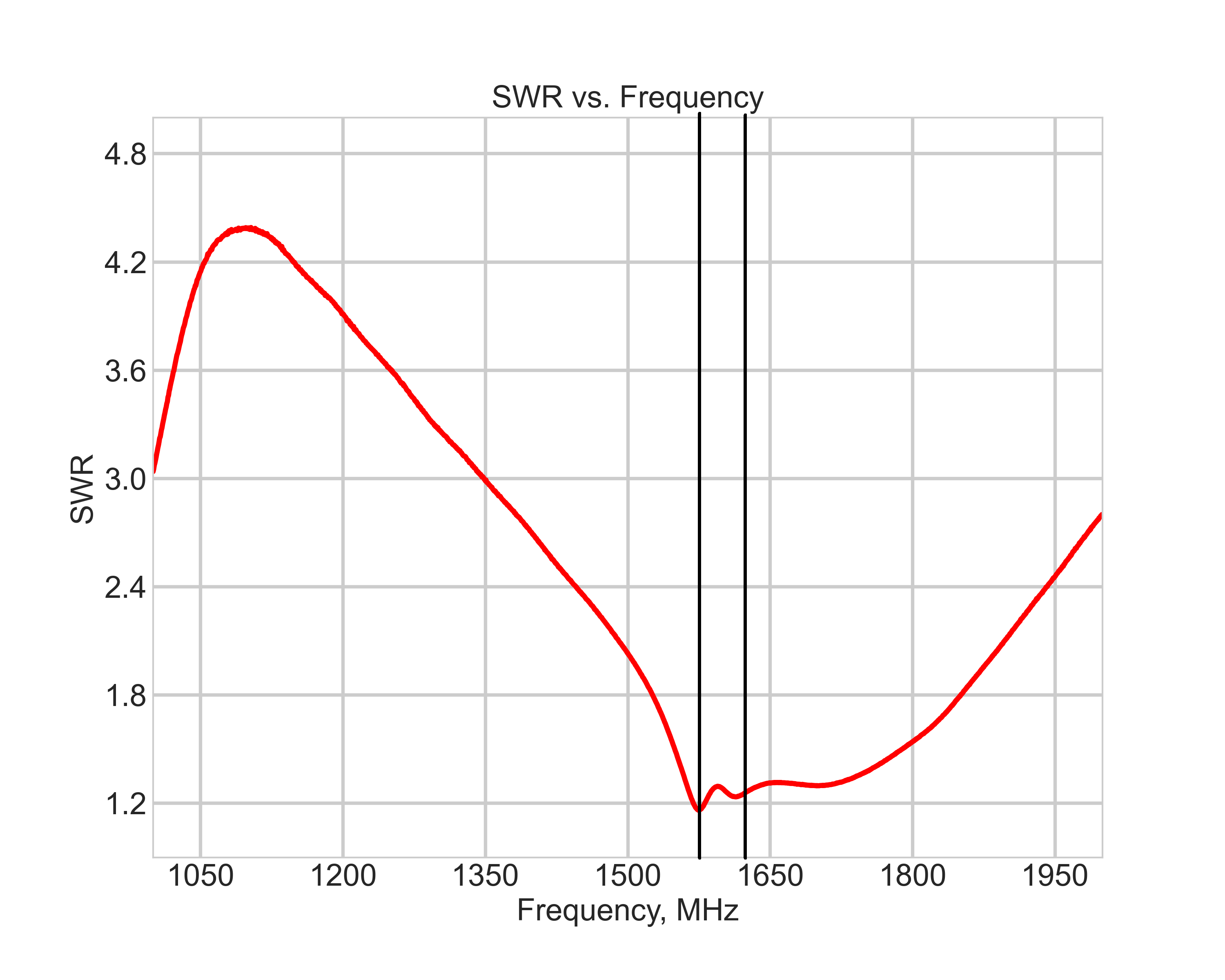
VSWR
The voltage standing wave ratio (VSWR) is a measure of the standing wave ratio that occurs on the transmission line of a radio frequency (RF) system. It is defined as the ratio of the maximum voltage to the minimum voltage of the standing wave along the transmission line. A VSWR of 1:1 indicates a perfect match, while a VSWR greater than 1:1 indicates that there is a mismatch between the system and the load.
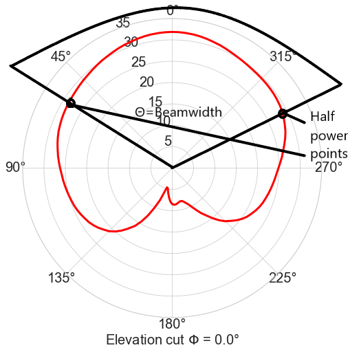
Beamwidth
The beamwidth of an antenna is the angular width of its radiation pattern. It is typically measured in degrees and is defined as the angle between the points on the radiation pattern where the power is at least half of the peak power. The beamwidth of an antenna is determined by its design and construction, and can be affected by factors such as the size and shape of its elements and the operating frequency. Antennas with a narrow beamwidth will focus their radiation pattern into a smaller area, while antennas with a wide beamwidth will produce a more diffuse pattern.
Bandwidth
The bandwidth of an antenna is the range of frequencies over which it can operate effectively. It is typically measured in hertz (Hz) or as a percentage of the center frequency, and is determined by the design and construction of the antenna. Antennas with a wide bandwidth can operate over a broad range of frequencies. The bandwidth of an antenna is an important factor to consider when selecting an antenna for a particular application, as it can affect the performance and range of the antenna. For example, a wideband antenna may be able to receive and transmit a broader range of signals, but may also be more susceptible to interference.
Phase center offset
The phase center offset of an antenna is the difference between the phase center of the antenna and its physical center. The phase center of an antenna is the point at which the phase of the radiated electromagnetic field is the same in all directions. The physical center of an antenna is the geometric center of its elements. The phase center offset can be affected by factors such as the design and construction of the antenna, and can vary with frequency.
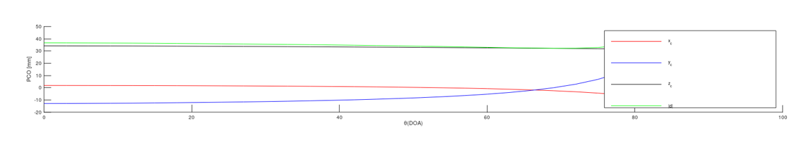
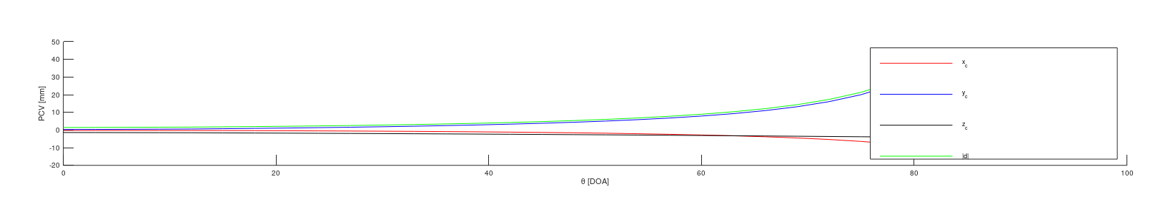
Phase center variation
Phase center variation (PCV) is the difference in the phase center of an antenna at different frequencies and angles. PCV is typically expressed in units of length and is a measure of the stability of the phase center of an antenna over a range of frequencies. Antennas with a low PCV will have a stable phase center, while antennas with a high PCV may exhibit variations in their phase center at different frequencies. The PCV of an antenna is an important factor to consider in the design and operation of antennas, as it can affect the performance and accuracy of the antenna.
LNA Gain
A low-noise amplifier (LNA) is a type of amplifier that is used to amplify very weak signals with a low level of noise. The gain of an LNA is a measure of the increase in the strength of the signal that it produces. It is typically measured in decibels (dB) and is calculated by comparing the power of the input signal to the power of the amplified output signal. An LNA with a high gain will produce a stronger output signal. The gain of an LNA is an important factor to consider when selecting an LNA for a particular application.
Noise Figure
The noise figure of a device or system is a measure of the amount of noise it adds to the signal it processes. It is typically expressed in decibels (dB) and is calculated by comparing the noise power at the output of the device to the noise power at the input. A device with a low noise figure will add little noise to the signal, while a device with a high noise figure will add more noise. The noise figure of a device is an important factor to consider when selecting equipment for a communication system, as it can affect the performance and sensitivity of the system.
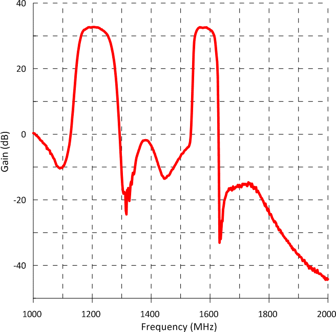
Out of band rejection
Out-of-band rejection is a measure of a device or system's ability to reject signals that are outside of its operating frequency range. It is typically expressed in decibels (dB) and is calculated by comparing the power of the signals within the operating frequency range to the power of the signals outside of that range. A device with a high out-of-band rejection will effectively reject signals outside of its operating frequency range.
Group Delay
Group delay is the time it takes for a signal to pass through a system or device. It is the difference between the phase of the input signal and the phase of the output signal at a particular frequency. Group delay is often used to describe the response of RF electronics systems to input signals and can be used to evaluate their ability to reproduce and process signals accurately. Depending on the design and operation of the system, the group delay may be constant or may vary with frequency. In some systems, it is desirable to have a flat group delay response across the operating frequency range, as this can improve the performance and clarity of the processed signal.
Group Delay Variation
Group delay variation refers to the change in the group delay of a signal over a certain frequency range. Group delay variation is important in many applications where it can affect the performance of systems such as filters and modulators. In general, systems with low group delay variation are desirable because they allow signals to pass through the system with minimal distortion.