Patch And Helix Antenna Comparison With Respect To Multipath Propagation
1. Patch antennas
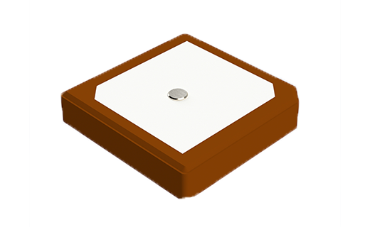
Patch antenna is the most common GNSS antenna type used in a large variety of civilian and military wireless systems. It consists of a flat conductive patch mounted on a dielectric substrate with a ground plane on the bottom side. Patch antennas are ideal solution where compact size and low cost of manufacturing is required. They can easily be integrated in handheld navigation devices such as phones and PDAs. Ceramic patch antennas are also very popular because of their huge variation of available sizes (40 x 40 mm down to 10 x 10 mm; typically 25 x 25 mm) making them versatile and adaptable. However, performance of a patch antenna is dependent on the ground plane size. As a result of fundamental physics, a smaller antenna will present a smaller aperture to collect the signal energy from the sky, resulting in a lower overall gain of the antenna. On the other hand, if patch is mounted on top of a large ground plane (i.e. 70 x 70 mm), it can exhibit high gain (around 10 dBi).
2. Helix antennas
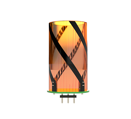
The quadrifilar helicoidal antenna (QFH) is widely used in different applications such as UAV/Drones, Unmanned Ground Vehicles (UGV), Unmanned Systems, High Precision Navigation, Military & Security, Smart Agriculture and Handheld GNSS Devices. It consists of a helical structure with four equidistantly spaced wire elements excited by currents with 90° phase difference, thus providing a circular polarization with very low axial ratio. Helicoidal antennas are typically used in applications where multiple antenna orientations are possible due to their wide elevation angle coverage. They are robust and demonstrate good navigational performance as well as resilience to multipath propagation. Helix antennas are usually small in size, lightweight and they don’t require a ground plane, which makes them very adaptable and easy to retrofit.
3. Advantages and disadvantages of patch and helix antenna
| ADVANTAGES | |
|---|---|
| PATCH | HELIX |
| Low profile and compact size | Lightweight |
| Ease of integration | Robust and durable |
| Relatively high gain and directivity for a single element GNSS antenna at low-elevation angles near the horizon | Wide elevation angle coverage (beamwidth |
| Requires only single excitation | Can be designed to achieve either omnidirectional or directional radiation pattern |
| Good versatility and adaptability | Good versatility and adaptability |
| Can be designed to achieve either linear or circular polarization | Exhibit circular polarization with very low axial ratio which improves resilience to multipath propagation |
| Low cost | Ground plane independent |
| Wide bandwidth | |
| Ability to acquire and track nearly all visible satellites provides excellent dilution of precision (DOP) | |
| DISADVANTAGES | |
|---|---|
| PATCH | HELIX |
| Ground plane dependent | Complex design and feeding (requires additional components to provide proper excitation of the elements) |
| Narrow bandwidth | Limited gain and directivity |
| Sensitive to dielectric properties, manufacturing tolerances, nearby objects and structures | Cylindrical shape and larger physical size make it unsuitable for some applications |
| Limited power handling | More expensive than patch |
| Relatively narrow beamwidth | |
4. Axial ratio and multipath rejection
When it comes to the evaluation of antenna’s performance, Axial Ratio (AR) is definitely one of the parameters to look at. Simply put, axial ratio is an indicator of purity of circular polarization. However, in order to get a better understanding of the term, let us first examine what is polarization in the first place.
Antenna polarization refers to the orientation of the electric field of the EM waves that an antenna transmits or receives. It can be either linear (where magnitude of the electric field follows a straight line with time), circular (where electric field draws a circular shape) or elliptical (most general shape, neither linear nor circular). Antennas are typically designed to transmit and receive radio waves with a specific polarization, and in order to get a best possible transfer of electromagnetic power from one point to another, it is important to ensure the same polarization of transmitting and receiving antenna. Furthermore, most satellite systems operate with circular polarization which can be either right-hand (RHCP) or left-hand (LHCP). As the name itself suggests, right-hand circular polarization follows the motion of the fingers of the right hand when the thumb is pointing outwards (clockwise rotation), while left-hand polarization has the opposite, counter-clockwise rotation.
This is where term axial ratio steps in nicely. It represents the ratio between the major and minor axis of the circular polarization pattern. And, as you can probably guess at this point, the smaller the difference between the two axis’, the more the pattern looks like a perfect circle. That is why an ideal circularly polarized antenna has an axial ratio of 1 (0 dB). In satellite communications low axial ratio is important for several reasons, one of which is multipath propagation.
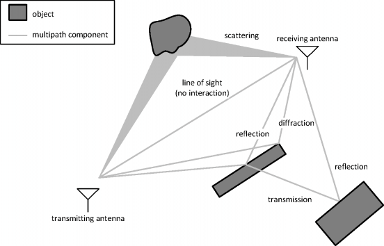
Multipath propagation is like a dance of electromagnetic waves taking numerous paths to reach their destination. As wireless signals travel through space, they encounter various objects and surfaces that act as mirrors, reflecting the signals in different directions. It's like a cosmic game of ping-pong, where signals bounce off buildings, trees, and other objects, creating an array of signal paths.
But, as with any game, there are consequences. These multiple signal paths, with their varied delays, amplitudes, and phases, can cause quite a commotion when they reach the receiver. It's like a symphony of interference, where the signals clash, overlap, and mingle in a chaotic dance. This interference can lead to signal fading, distortion, and even data errors.
For that reason, polarization purity of an antenna evaluated by axial ratio is of vast importance to mitigate the effect of multipath propagation in satellite communication systems. Namely, circularly polarized electromagnetic waves tend to change their polarization as they reflect from conductive surfaces. Right-hand circularly polarized wave reflects as left-hand circularly polarized, and vice versa. It is like looking at your reflection in the mirror, the image you see is inverted. Antennas with very low axial ratio thus reject reflected, destructive signals much better than the antennas with high axial ratio. For instance, ideal right-hand circularly polarized antenna with an axial ratio of 0 dB completely rejects all the reflected left-hand circularly polarized waves, thus ensuring best quality of the signal and no data loss.
Quadrifilar helical antennas excel in that sense, exhibiting among the lowest axial ratios of all commercially available antennas, over broad band of frequencies and for various different applications. Their cylindrical shape goes naturally with circular pattern of the electric field needed for the purest circular polarization. On the other hand, patch antennas with a fairly large ground plane provide somewhat higher gain values which means they have better rejection of the signal coming from the horizon (that is where reflected signals are often coming from). However, in such case multipath propagation will play a larger role when reflections come from angles closer to zenith (for instance in a place with a lot of towers and high buildings). All things considered, in systems where rejection of multipath propagation is of crucial importance, helical antenna is your weapon of choice, while in systems where higher gain and low profile is more appreciated, patch antenna should be considered.